Braking energy recovery technologies have recently become a new market for the public transport sector and the industry has been investing in research and development in this field. Different technologies are competing for the same sector, with no clear leading technology. Each technology has advantages and drawbacks, depending on each context.
T2K partners have thoroughly investigated braking energy recovery technologies. Three of the T2K partners have simultaneously implemented systems on their network. This joint approach is unmatched anywhere in the world and allowed them to gain significant expertise in this field. It emerges that investing human and financial resources in this concept is worth the effort, as it can substantially improve the energy efficiency of urban rail networks.
Concept
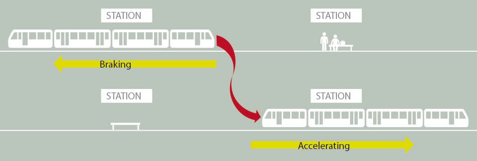
Rail vehicles are propelled by electric motors supplied by substations placed along the tracks. The electricity is transferred via an overhead line through the pantograph in the case of a tram, and by a third rail running all along the track in the case of a metro. Most recent rail vehicles have the ability to brake electrically using regenerative braking techniques. In that case, the electric motor can work as a generator recovering the vehicle’s kinetic energy and converting it into electricity.
Fig. 34 – Concept of the regenerative braking on a rail network

In these vehicles, while a small portion of this kinetic energy can be reused to power vehicles auxiliaries, the remaining energy can be sent back to the network and hence recovered only if a vehicle is accelerating nearby. In this case, the accelerating vehicle takes advantage of this energy transfer. If that is not the case, the network voltage increases due to the energy surplus and this extra energy has to be dissipated in braking resistors. This principle is shown in the figure above.
These energy transfers between vehicles depend on parameters such as the traffic density, distances between the stations or slopes. In a metro network, these transfers usually amount to 20-30% of the total consumption.
However, in many situations, the energy cannot be recovered on the network because no vehicle is accelerating exactly when another is braking. To avoid these energy losses and to reduce overall energy consumption, several applications have been developed.
Applications
Braking energy recovery applications can be classified in three families:
- Mobile storage applications Braking
- Stationary storage applications
- Stationary ‘back to the grid’ applications.
Mobile storage applications
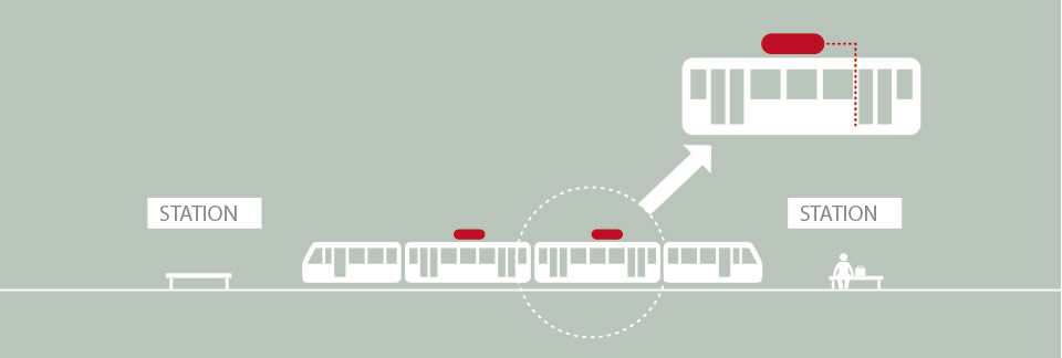
Fig. 35 – Concept of a mobile energy recovery system placed on the vehicle
Mobile storage applications consist of onboard energy storage systems (ESS), usually located on the vehicle roof, every system working independently. When the recovered energy cannot be used by another vehicle nearby, the energy is directly sent to the storage system placed on the vehicle. The stored energy is then used to power the vehicle when it accelerates or supply its auxiliaries (heating, cooling, lighting, etc).
Stationary storage applications
Fig. 36 – Concept of a stationary energy recovery system placed along the tracks
Stationary (wayside) storage applications consist of one or several energy storage systems placed along the tracks. They can recover the energy from any braking vehicle and power any accelerating vehicle.
Stationary ‘back to the grid’ applications
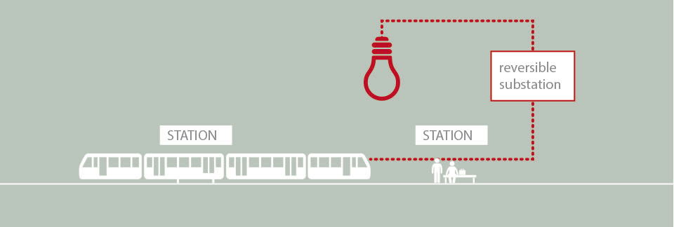
Fig. 37 – Concept of a reversible susbtation (inverter) sending the recovered elecricity back to the grid
The main difference with the previous applications is that ‘back to the grid’ applications do not store the recovered energy. Instead they send it to the main electrical grid to be used by other consumers or potentially sold back to the energy distributors.
Applications comparison
Table 8 – Comparison of braking energy recovery applications for urban rail vehicles
| Mobile storage systems | Stationary storage systems | Reversible substations | |
|---|---|---|---|
| Overhead line or third rail losses are reduced. | x | ||
| High efficiency due to lower transformation and storage losses. | x | ||
| Recovered braking energy can supply any equipment (lighting, escalators, etc.). |
x | ||
| Vehicles can be operated without overhead lines/ third rail on short sections. |
x | ||
| The systems can be installed without having to modify the vehicles. | x | x | |
| Lower safety constraints as not on-board of the vehicle. | x | x | |
| Tunnels and stations warming can be avoided by reducing the heat produced by the braking resistors. |
x | x | x |
| Voltage stabilisation and peak-shaving opportunities. | x | x |
Each type of application has advantages and drawbacks summarized in the table above.
Technologies
The previously described applications can be based on different technologies:
- A battery stores energy through an electrochemical reaction. Batteries are found in a large range of sizes and power ratings.
- A supercapacitor is an electrochemical storage device where the energy is stored as a concentration of electrons on the surface of a material. No chemical reaction occurs. They bridge the gap between conventional capacitors and batteries and can deliver at least 10 times higher power than most batteries of equivalent size.
- A flywheel is a rotating wheel spinning around an axis, used for storing energy mechanically in the form of kinetic energy. The flywheel works by accelerating a rotor to a very high speed and maintaining the energy in the system as rotational energy. Flywheels can be used to produce high power peaks.
- Most conventional substations allow only for unidirectional energy flow. A reversible substation uses an inverter allowing the energy to flow in both directions. Unlike the storage technologies described previously, the recovered braking energy is not stored but sent back to the electrical network.
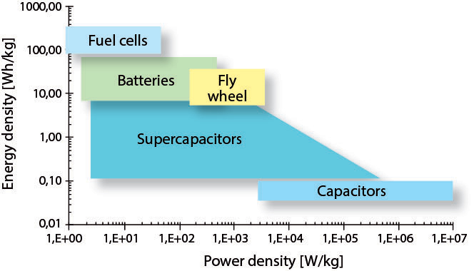
In terms of power and energy density, the different storage technologies perform differently. Supercapacitors have a relatively low energy density but a high power density (fast electrical response) whereas batteries have a high energy density but a low power density (slow electrical response). Flywheels have also a relatively high power density.
Implementation
Both mobile and stationary systems aim to reduce the overall consumption of metro and light rail networks. Only a very limited number of systems have yet been implemented in the public transport field worldwide.
Most systems are still at the prototype stage, which makes it difficult for transport operators to take investment decisions due to the lack of experience feedback and uncertainties about the return on investment and life cycle. Costs could decrease when this market expands, as a result of technological improvements and a reduction in material costs.
Fig. 38 – Comparison of storage technologies

Throughout the Ticket to Kyoto project, the partners demonstrated that it is not easy to compare technologies, assess likely performance and determine the optimum technological solution. Finding the best-adapted technology and opting for the right implementation require a holistic approach that takes many parameters into consideration.
One key element when investigating braking energy recovery technologies is simulation. A comprehensive analysis of the network and a clear evaluation of possible gains are recommended. Most suppliers will offer their services and experience in this field. However, results might be affected by their obvious interest in selling their own devices, which might not always be the most appropriate. Other consultancies are also developing simulation tools for this purpose and may offer more neutral assessments.
Issues
Any operator willing to invest in a braking energy recovery system should at least consider the following issues as they will have straight impacts on the energy savings and the way systems can be implemented.
Network issues
- Electrical network ownership
- Configuration of the electrical network
- Traffic intensity
- Line topology
- Type of vehicles
- Weather and temperature.
Implementation issues
- Location choice
- Number of systems
- System size and weight
- Cooling and ventilation requirements
- Weather and temperature effects.
Environmental issues
- Use of harmful materials
- Noise and vibrations
- Electromagnetic interference.
Financial issues
- Investment costs
- Lifetime
- Life cycle costs (maintenance and replacement)
- Return on investment.
